Mitsubishi Eclipse 4G Forums banner
14K views 14 replies 4 participants last post by  Z0|v|Bi3  
#1 ·
Dear Friends,

Months ago, I had de P0174 System Too Lean Bank 2.

My car had the following symptoms:
- When starting the car from being cold, AFR goes quite lean (> 18) only after a few seconds of being Idle - After giving little gas, AFR suddenly goes lean (15 - 17)
- Sometimes with gentle acceleration, AFR progressively increases one unit by second from 14 to 18. When it reaches 18 in one second ECU enriched mixture and drops to 14.
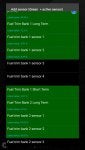
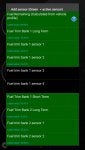
- When the above symptoms occurs in my OBD2 scanner, FuelTrim for Bank 1 is 1-1.5% and FuelTrim for Bank 2 is -25% (ECU leans the mix), both ends!
- After driving few miles FuelTrim is more stable but leans at low accelerating.

There is no other code but only the P0174. I have Magnaflow Cat Back Exhaust, CAI INJEN, OBX Long Tube Headers (Cat was removed), AEM FIC and AEM Fail Safe Wideband.

In my scanner Front Sensors (Bank 1 Sensor 1 And Bank 2 Sensor 1) Oscillates between 0 to 9 volts as expected.

Possible solutions I tested:
- Front O2 sensors are connected directly to ECU and is not intercepted by AEM FIC.
- I Disabled Rear O2 Sensors with Hackish reflash.
- I swap front O2 sensors.
- I clean Injectors.


When I Swap the front O2 sensors, I expect to get P0171 Code (System too lean Bank 1) when there is a problem with the bank 2 O2 sensor - but the P0174 Code appears again!!!

Why does ECU lean mix (FuelTrim -25%) only for Bank 2?

Is it not injectors or fuel filter because Bank 1 is not lean only Bank 2, neither a leak because ECU FuelTrim is -25% for Bank 2.

If you had any ideas or suggestions you can share, I would greatly appreciate it:

Thanks in advance.
 
#2 ·
Welcome to Club4G.org Gastavo.

The only time we use the AME FWIC these days if we are going Turbo, or Super Charger. These days everyone is going with the Hakish Tune alone. Lets face it, you are using two tuning systems and this could cause problems when tuning. I'm not going to say this is your problem, but it could cause problems especially if you have a wiring problem with your FWIC wires.

I don't know if you have the Eclipse Factory Service Manual, if not I'll provide a link for it. The area that will be dealing with in these books has broken links, so you will need to download this manual onto your computer to have access to all the files in this manual. Sorry, I can't help this but it worth the information gained. At the very top of this link you will see a link that will download the manual to your computer, press this link and it will download the manual to your PC, then unzip this file and it will create a PDF file with all 46 books. You will need a PDF reader like Adobe Acrobat, which is also a free download.

Eclipse Factory Service Manual Link:
http://tearstone.com/2006-eclipse-factory-service-manual/

Look For:
Offline Download
2006 Eclipse FSM Full Download

This link will download the service manual to your computer.
 
#3 ·
GROUP 13A MULTIPORT FUEL INJECTION (MFI) 2.4L ENGINE>
DIAGNOSTIC TROUBLE CODE CHART Page 13A-41
P0174 System too lean (cylinder 2, 3) Page 13A-425 (Broken Link)
In download manual, PDF Flie GR00005800B-13, Page 13A-425

This is just a shot version, I can't copy and past all the pages concerning this problem:

DTC P0174: System too Lean (cylinder 2, 3)
CAUTION
If DTC P0174 has been set, TCL related DTC U1120 is also set. After P0174 has been diagnosed, don't forget to erase DTC U1120.
.
Fuel Trim Circuit
•Refer to DTC P0202 − Injector Circuit-cylinder 2 P.13A-479, DTC P0203 − Injector Circuit-cylinder 3 P.13A-490.
.
CIRCUIT OPERATION
•Refer to DTC P0202 − Injector Circuit-cylinder 2 P.13A-479, DTC P0203 − Injector Circuit-cylinder 3 P.13A-490.
.
TECHNICAL DESCRIPTION
•If a malfunction occurs in the fuel system, the fuel trim value becomes too large.
•The ECM <M/T> or the PCM <A/T> checks whether the fuel trim value is within a specified range.
.
DESCRIPTIONS OF MONITOR METHODS
Cylinder 2, 3 air/fuel learning value (long time fuel trim) and air/fuel feedback integral value (short time fuel trim) are too lean.
.
MONITOR EXECUTION
Continuous
.
MONITOR EXECUTION CONDITIONS (Other monitor and Sensor)
Other Monitor (There is no temporary DTC stored in memory for the item monitored below)
•Misfire monitor
Sensor (The sensor below is determined to be normal)
•Mass airflow sensor
•Engine coolant temperature sensor
•Intake air temperature sensor
•Barometric pressure sensor
•Throttle position sensor

TROUBLESHOOTING HINTS (The most likely causes for this code to be set are:)
•Mass airflow sensor failed.
•Injector (Number 2, 3) failed.
•Incorrect fuel pressure.
•Air drawn in from gaps in gasket, seals, etc.
•Engine coolant temperature sensor failed.
•Intake air temperature sensor failed.
•Barometric pressure sensor failed.
•Manifold absolute pressure sensor failed.
•Exhaust leak.
•Use of incorrect or contaminated fuel.
•Harness damage in cylinder 2, 3 injector circuit or connector damage.
•ECM failed. <M/T>
•PCM failed. <A/T>


STEP 1. Check for exhaust leak.
Q:Are there any abnormalities?
YES :
Repair it. Then go to Step 14.
NO :
Go to Step 2.

STEP 2. Check for intake system vacuum leak.
Q:Are there any abnormalities?
YES :
Repair it. Then go to Step 14.
NO :
Go to Step 3.
STEP 3. Using scan tool MB991958, check data list item 10: Mass Airflow Sensor.
AK500051ABDATA LINKCONNECTORMB991824MB991827MB991910
CAUTION
To prevent damage to scan tool MB991958, always turn the ignition switch to the "LOCK" (OFF) position before connecting or disconnecting scan tool MB991958.
(1)Connect scan tool MB991958 to the data link connector.
(2)Start the engine and run at idle.
(3)Set scan tool MB991958 to the data reading mode for item 10, Mass Airflow Sensor.
(4)Warm up the engine to normal operating temperature: 80°C to 95°C (176°F to 203°F).
•When idling, between 1,300 and 1,620 millivolts.
•When 2,500 r/min, between 1,600 and 1,970 millivolts.
(5)Turn the ignition switch to the "LOCK" (OFF) position.
Q:Is the sensor operating properly?
YES :
Go to Step 4.
NO :
Refer to DTC P0101 − Mass Airflow Circuit Range/Performance Problem P.13A-130, DTC P0102 − Mass Airflow Circuit Low Input P.13A-141, DTC P0103 − Mass Airflow Circuit High Input P.13A-151.
STEP 4. Using scan tool MB991958, check data list item 5: Intake Air Temperature Sensor.
AK500051ABDATA LINKCONNECTORMB991824MB991827MB991910
(1)Turn the ignition switch to the "ON" position.
(2)Set scan tool MB991958 to the data reading mode for item 5, Intake Air Temperature Sensor.
•The intake air temperature and temperature shown with the scan tool should approximately match.
(3)Turn the ignition switch to the "LOCK" (OFF) position.
Q:Is the sensor operating properly?
YES :
Go to Step 5.
NO :
Refer to DTC P0111 − Intake Air Temperature Circuit Range/Performance Problem P.13A-193, DTC P0112 − Intake Air Temperature Circuit Low Input P.13A-202, DTC P0113 − Intake Air Temperature Circuit High

And the t-shooting just goes on from here, just way to much for me to copy and past... Also you can see all the other references that takes you to other parts of this book as well as others. I know it also asks for a scan tool, still most of these T-shooting procedures can be use without the scan tool.
 
#4 ·
Cylinders run from left to right, 1, 2, 3, 4.

Cylinders 2, and 3, are your two-center tubes

O2 sensors for cylinders 2, and 3, are located on the right-side of your headers.

It sounds like you are a smart mechanic, but I have to ask these questions:

When installing your headers, did you use a torque wrench when installing the header plate to the exhaust ports/head?? Improper torquing can/will cause the header plate to warp and cause an exhaust leak. Once the header plate is warped it can/will never seal properly without the use of a crush gasket.

Did you have to extend any of your O2 Sensor harnesses?? When extending these harnesses you must either use a proper pin system, or solder the wires with the proper solder made for steal wires!! Also there are four-wires per O2 sensor, these wires must be matched!! There are two ground wires, these ground wires CAN NOT be switched. There are two independent circuits in each O2 Sensor, by switching the ground wires you will get false readings from the two circuits.
 
#5 ·
:(

Thanks Clovisman for your response. In regards to your advices, there are some considerations that I didn't mention (hubo consideracion que no las mencione?).

- I have the service manual, the P0174 Code is set when maximum FuelTrim is applied (-25). In theory, ECU leans mix when a richer condition has found. But I don't know where this procedure is in the service manual (For FuelTrim diagram).

- The problem was that before Hackish Flash.
- The FIC is temporal until ECU Reflash will be more stable.
- Headers was installed using a gasket.
- I did not need to extend O2 Front Sensors harness.

By swaping the front sensors, the car improved significantly but it still remains a failure but with a lot less lean mix and P0174 appears again after a few miles.

It's very strange.

:(
 
#6 · (Edited)
Thanks Clovisman for your response. In regards to your advices, there are some considerations that I didn't mention (hubo consideracion que no las mencione?).

- I have the service manual, the P0174 Code is set when maximum FuelTrim is applied (-25). In theory, ECU leans mix when a richer condition has found. But I don't know where this procedure is in the service manual (For FuelTrim diagram).

- The problem was that before Hackish Flash.
- The FIC is temporal until ECU Reflash will be more stable.
- Headers was installed using a gasket.
- I did not need to extend O2 Front Sensors harness.

By swaping the front sensors, the car improved significantly but it still remains a failure but with a lot less lean mix and P0174 appears again after a few miles.

It's very strange.

:(
First, what are you using to control your fuel right now, the FWIC, or the ECU?? You can not use both.

We have had this problem with several GS models with similar setups, but none of them ever replied with a fix. NONE were using a FWIC, just the ECU.

You did not answer the question whether you used a torque wrench, I can not stress how important a torque wrench is when working on this engine and/or vehicle. Time and time again I've seen people put there engine parts back together without a torque wrench and proper torque pattern and they end up with a vacuum leak.

I do not know your mechanical background so I have to ask questions that might seem pretty simple and basic. I have 23 years of aircraft maintenance experience, and have been working on cars since the early 70's. I only know how to do maintenance one way, and one way only.

Has the following been checked, these are the most likely causes for this code.

TROUBLESHOOTING HINTS (The most likely causes for this code to be set are)
•Mass airflow sensor failed.
•Injector (Number 2, 3) failed.
•Incorrect fuel pressure.
•Air drawn in from gaps in gasket, seals, etc.
•Engine coolant temperature sensor failed.
•Intake air temperature sensor failed.
•Barometric pressure sensor failed.
•Manifold absolute pressure sensor failed.
•Exhaust leak.
•Use of incorrect or contaminated fuel.
•Harness damage in cylinder 2, 3 injector circuit or connector damage.
•ECM failed.
•PCM failed.
 
#7 ·
Clovisman,
Headers were placed in the center of the exhausts. I was present when they used the torque wrench. Fuel is controlled by FIC, but this doesn't still explain why the ECU is set a FuelTrim of -25 only for bank 2. FIC puts the same Fuel in all cylinders and there is no option to put independent fuel by cylinder. I did test to set no modifications in FIC and use solely ECU configuration and there's stills the problem.

•Mass airflow sensor failed.
•Incorrect fuel pressure.
•Air drawn in from gaps in gasket, seals, etc.
•Engine coolant temperature sensor failed.
•Intake air temperature sensor failed.
•Barometric pressure sensor failed.
•Manifold absolute pressure sensor failed.
•Exhaust leak.
•Use of incorrect or contaminated fuel.

These causes cannot be because Bank 1 doesn't fail. Generally for example "Mass airflow sensor failed" affects Bank 1 and Bank 2, but there is no P0171 (For bank 1) code - only for P0174

Maybe there's an leak in one of the exhausts in the Headers. That would explain why O2 sensor senses a rich condition and ECU accordingly leans the mix for Bank 2 only. I will check leaks and the O2 sensor harness.

Gustavo.
 
#8 ·
Okay, I understand were you are coming from, but this vehicle can do some weird magical things to tell you something is wrong and still not through a code, for instance: A anti-skid light on the dash points to the MAF/IAT Sensor, no codes, but time, and time again we change the MAF/IAT Sensor and the light goes away. This was found many years ago when our car was still relativity still new, if you didn't know this, guess what, you would be t-shooting the brake system for months.

Like I said, we have had several GS models in the past year that have thrown the same code (P0174) with the same basic setup as your's. You are correct in thinking, if it was the MAF then cylinders 1, and 4, should be throwing the same code. However, if you were trying to save wire, then you only need one reading, so what if the reading is only taken from the left Bank, cylinders 1, and 3. I'm just trying to think out of the box.

Start with something simple like a good injector cleaner, if injectors are dirty, leaking, or stuck it could/will cause a problem. It happen to me once a long time ago on a new car, so anything is possible, and it cost less then $10 for a good injector cleaner.

If available in Bolivia, use Marvel Mystery Oil. Back in my street racing days back in the 70's, we used this stuff like liquid gold, especially for cleaning and break-in oil. It will free stuck lifters, rings, great for cleaning and lubricating the fuel system and pump, and so much more. You can also add to engine oil. I forgot about it when I joined the air force, and just recently began to use it again. ::Marvel Mystery Oil::

By the way, the Mass Air Flow Sensor, and Air Intake Temperature Sensor are one in the same, they are both located on the same sensor, The MAF/IAT sensor.
 
#10 ·
These pic's will not help, I'm not sure what you are using for a diagnostic machine/computer, the one we would use if affordable would be the one that Mitsubishi would use... and nobody seems to be able to afford that equipment, I believe that last time I looked into that equipment we would be looking at between $5000 to $7000 to buy a Mitsubishi computer with software.

For us there is no sensor 3, or 4, on our engines, so it doesn't help me to resolve your problem. As far as the little jumps you are having in the video, I could call that a normal idle, all idles will jump a little, now if it was jumping for 14 down to 7, and back to 18, I would say you have a problem. Your main concern would be what it is doing under power, I.E. Bank 1 is reading 14, while Bank 2 is reading 12, now that would be reading a significant difference between Banks.
 
#14 ·
wait hackish posted this:


this guy knows more about 4g then anyone ive ever seen:


Senior Member


Name: Michael
Join Date: Mar 2009
Location: pays du Québec
Posts: 1,089
Rep Power: 9
hackish is just really nicehackish is just really nicehackish is just really nice

Be careful as a number of O2 sensors use stainless steel wire and you can't solder it. I've had better luck using heatshrinkable (weatherproof) butt connectors. Another trick that helps is to skin about 1/2" of wire, twist it then fold it over before putting the required 1/4" piece into the butt connector. This helps to stop it from slipping out when crimped.

Generally switching the black wires don't matter for polarity since they only go to a heater element and it doesn't care which one is ground and which one is power. Doesn't take too long to keep them matched up so do that anyway...

-Michael
hackish is offline Add to hackish's Reputation Report Post Reply With Quote